A ventilation model must have a number of key components to successfully run.
Some Simple Rules for Constructing a Model are:
- All airways in a model must be connected at both ends to another airway, unless connected to the surface or ‘blanked’ off as a closed end.
- A model must have a device(s) to produce pressure within the model and induce airflow. Pressure producing methods use in Ventsim Visual™ includes placing fans or a fixed airflow or pressure within an airway.
- Any fixed flow in an airway must not restrict another fixed flow elsewhere in a model, or be overly restricted by an impassable high resistance.
Errors contributing to the above conditions account for around 90% of simulation errors and problems noted in Ventsim (from Chasm Consulting observations)
There are many different ways to build a computer ventilation model. Ventsim Visual™ (as the name suggests) utilises a visual approach to creating models, and the fundamental structure (shape) of models can be built either by hand with the mouse, or imported from a CAD program.
While a ventilation model can be built schematically in Ventsim, it is highly recommended building a true to scale 3D model if possible, to allow Ventsim to automatically use parameters such as size, length and depth for simulation. For compressible airflow models, this allows for automatic density adjustment and natural ventilation pressure application, resulting in more accurate and realistic results. In addition, rock temperature and autocompression can be automatically calculated for heat simulation.
A ventilation model must have a framework of connected airways or branches. For airflow to successfully travel along an airway, each airway must have a connecting airway at the entry and exit. Airways with no connection at either end will not carry airflow unless connected to the surface.
Model Types A ventilation model can be developed as either a closed or open model.
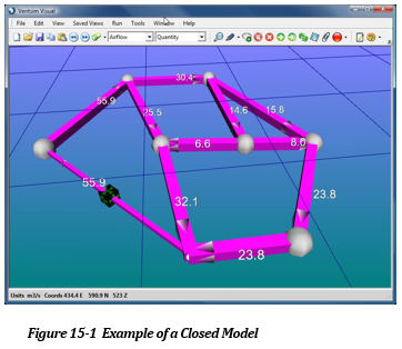
Closed Model
A closed model does not have any airways connecting to the surface. While this would be unusual for a real mine, for diagnostic purposes it is possible to build and simulate an entirely closed model, which continually circulates air around the modelled airways. To construct a closed model, simply connect and loop all airways so that they form a continuous path and all airway ends are connected to at least one other. Because a closed system is entirely self-contained, pressures and energies placed within the model to distribute flows are entirely consumed by the airways in the model. No ventilation energy is lost to outside sources.
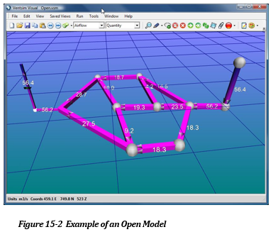
Open Model
An open model has at least two airways which connect to the surface, at least one of which is an intake airway, and another which is an exhaust airway. Most (if not all) mines will be established as open models. Airflow that exits an exhaust airway, in no way influences the pressure (or temperature) of the airflow which enters an intake airway. Airflow velocity pressures and energies lost from an exhaust airway are assumed lost to the model system. To link any airway to the surface, simply use the Connect to Surface function under the Edit Form.
Airways can be constructed in a number of ways.
- Manually draw scaled airways with the mouse using the toolbar functions.
- Manually draw schematic airways with the mouse using the toolbar functions.
- Import airway data from a formatted spreadsheet using the TXT import function.
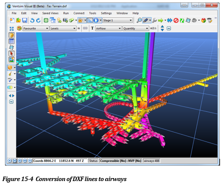
- Import graphics data from a DXF/DWG/ Datamine / Surpac graphics file into Ventsim, and convert the data to airways. Most mine planning and CAD packages will have the ability to export data to one of these formats.
Regardless of the method used, in summary the recommended steps for constructing a ventilation model are as follows:
- Construct the airways either manually using the DRAW function, or via the IMPORT function, ensuring all airways join correctly to each other. Filter tools are available in Ventsim to assist with ensuring airways are joined together.
- Use the EDIT button to edit the airways that connect to the surface, and mark SURFACE optionon the form.
- Again, using the EDIT button, set the correct size and shape for all airways. Insert any ventilation controls or regulators in the model, and specify airway characteristics such as friction factors and shock losses.
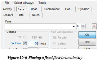
- Place a FAN or FIXED flow in an airway again using the EDIT button, and selecting the FAN tab of this form. This will provide pressure to drive the airflow through the model
- Finally, press the SIMULATE button to show the result of the model construction. If everything has been constructed correctly, the airflow data and arrows should show the result of the simulation.
- If some airways are dead ends, then simulation warnings can be prevented by setting the “CLOSED END” option in the airway EDIT form.
- If any error or warnings show, then correct the mistakes individually or grouped as required.
Manual Scaled Construction To manually construct airways, simply use the construction tools (the draw, move, copy and delete buttons) from the toolbar.
Airways can be drawn freehand on the screen with the mouse, using the coordinates displayed in the status bar to guide the airway location. Additionally, coordinates for airways can be entered manually using the coordinate entry function or by simply clicking on an airway end while in the draw mode.
This method is generally suitable for small models (less than several hundred airway segments). Most airway models are generally fairly tolerant of misaligned or slightly misplaced airways, providing approximate airway lengths are close to reality. In many cases, to assist with clarity, airways can be deliberately moved aside, and a fixed length function used to override the automatic length calculation to set actual lengths.
If the model is required to be true to scale, then more accurate construction may be required, and it is often better to import actual mine designs from CAD programs into Ventsim to use as a template to constructing a true to scale model.
In some cases, a model schematic can be constructed to simulate a model. A model schematic may look nothing like a real mine, but simply represent airways by a series of conveniently located two dimensional lines. Correct airway lengths can be entered by fixing the length under the Edit From.
Warning: Schematic Models, although convenient in simplifying mine airway models, have major restrictions which can affect their functionality in Ventsim Visual. Ventsim Visual™ uses true airway locations to calculate changes in air density and heat properties of rock and airflow, and as such, schematic models are largely unsuitable for Ventsim Visual™ Advanced models which simulate deep mines with compressibility effects or for heat simulation.
Where a list of airway coordinates and sizes may be available (from a database or another ventilation program for example), these can be directly imported into Ventsim Visual™ using the File Open Text Function. Data to be imported must meet a specific TAB delimited data format. This format can be loaded and saved by most office application software such as Microsoft Excel or Word. This format can be viewed by saving any existing model file as a TXT file format under the save menu.
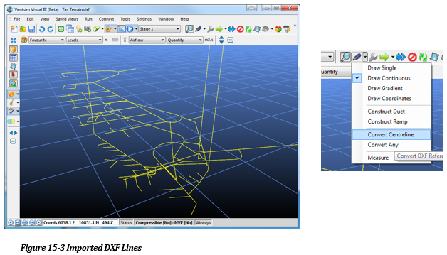
STEP 1 – Create and Import a DXF file into Ventsim Visual
This method relies on passing line or string graphics data from a CAD or Mine Planning package to Ventsim Visual. The data may simply be the centre lines of surveyed mine floors or mine designs. To allow Ventsim Visual™ to efficiently use this data without excessive post import editing, the following criteria should be considered.
- Only import the minimum data required. Excessive detail or headings which do not form part of the ventilation model should not be imported if possible. In many cases, is may be quicker and more accurate to construct a skeleton ventilation model consisting of interconnected lines within the Mine Planning or CAD package, before import into Ventsim Visual. The skeleton lines should simply trace over existing mine workings or designs.
- Try to ensure the lines join into each other, so Ventsim Visual™ knows they are junctions through which air can flow. Lines that simply cross each other without a junction, or which terminate close to each other but not join, will not carry airflow, and may result in a no exit/entry error in Ventsim which will need to be corrected in Ventsim.
When importing data, the lines can be converted to airways during the import process (by selected the option “Convert to airways’), or selectively after importing using the DRAW > CONVERT button to click or fence which lines are to be converted. The second option has the advantage of overlaying the updated DXF files with new development over the existing Ventsim airways, and selectively choosing where to update the Ventsim model.
Hint : To efficiently add DXF data to Ventsim Visual, keep a ‘layer’, ‘object’ or ‘file’ within your Mine Planning or CAD package dedicated to Ventsim Visual™ data, As new airways or designs become available, simply export the additions as separate DXF files, and import them into Ventsim Visual™ to add to the existing model.
Warning: Three dimensional solids (such as survey mine solids) will import into Ventsim Visual, but cannot directly be converted to airway. They can however be used as a guide to manually draw and construct new airways in the model
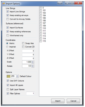
STEP 2 – Modifying and Validating Import Data
Once imported into Ventsim Visual, the program will assign default airways sizes and shapes to all the imported airways. Ensure you have default sizes and shapes set in the Settings menu that will approximate the typical sizes that are imported. This will prevent having to re-edit of ALL of the airway sizes and shapes (although this can still be quickly done using the group edit command)
Import DXF Graphics Solid or Wireframe Data
Unlike line string data, solid or wireframe graphics cannot be directly converted to airways. The data can still however be used to help construct airways, by either using the referenced (imported) graphics as guides to manually draw airways, or by using a special function in Ventsim to group the data and construct an airway of best fit through the data.
OPTION 1 – Turn on Edit > Lock on References menu option and select the DRAW button.
Simply use the mouse to DRAW airways over the top of the imported graphics. The airways will ‘connect’ to the same position as the reference graphics (providing the Edit > Reference Lock is enabled), allowing the ventilation model to be drawn in true 3D coordinates.
OPTION 2 – Convert ANY (references to airways). Use the Draw Sub-Option > Convert Any.
This option converts groups of referenced graphics to an expected airway path, and may be of use to attempt to convert large amounts of wireframe or multiple string (for example floor outlines) to an expected airway. It is likely that significant editing may be required after using this function to adjust airway locations and correct errors. For further information on this method see Convert Any option.
To quickly sort and validate (check) the imported airways, click on airflow simulation. While the model is unlikely to correctly simulate at this stage, this function will check the airways for duplicates and unconnected airway ends, which will speed up the process of establishing a working model.
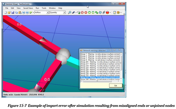
In most cases, errors will result from airways not exactly joined into other airways, or remaining unconnected as dead ends, resulting in no exit or entry errors. If many of these can be corrected before starting an airflow simulation, this will improve the ease of creating a working model.
Filtering Tools
To help tidy up models and correct initial errors, a number of tools are provided in the TOOLS > FILTER menu, to bind disconnected airways, and find duplicated airways.
Alternatively, for airways which are disconnected use the toolbar move function to move the airway end onto the other junctions ends. If this is done correctly, moving the node after joining will then result in all airway ends moving simultaneously.
Under Tools > Utilities > FILTERING TOOLS
BINDING : Bind Nodes (use a value up to 4-5m or more to bind ends that are close to each other). Bind Junctions (Binds loose nodes that are close to a passing airway which has no corresponding node or junction). Bind Intercepts (find and/or join airways that cross each other, but have no joining nodes)
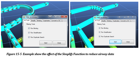
SIMPLIFY (removes a lot of the small airways and unnecessary detail). In many cases, importing a DXF files directly from a mine planning will create an overly detailed model file, which will slow down the system graphics and simulation, resulting in a more unwieldy model.
For example, a nice smoothly rounded decline airway which produces many airway segments is simply not required for accurate ventilation simulation and in most case can be designed with less segments and detail. The Simplify function in Ventsim Visual, will sort through a model, identifying unnecessary detail, which can be removed without adversely affecting simulation.
Alternatively, airways can be manually simplified by using the toolbar delete function to remove node junctions between airways.
DUPLICATES (find and/or remove any duplicated or overlapping airways)
To produce pressure within a model to motivate airflow, the following three methods can be used.
- Fans : Utilise and fan curve to establish accurate working flows and pressures in a ventilation model.
- Fixed Pressures : Use a consistent pressure to induce an airflow in a ventilation model. Airflow will vary based on resistance encountered by the pressure.
- Fixed Airflows : Use a consistent airflow to induced flow through a model. Pressure required will be adjusted to whatever is required to produce the airflow.
Without at least one of the above methods to produce model pressures, airflow will simply remain stagnant.
In Ventsim Visual™ Advanced, a fourth method uses natural ventilation pressures to also induce flow, although this is entirely derived from heat and density air changes throughout the mine. It is possible to build a ventilation model with airflow driven entirely by geothermal heat or evaporative cooling, however the simulation results can sometimes be unreliable due to changing airflow and pressures continuously affecting natural ventilation pressures.
A fan can be selected to simulate flow in a model. Fan curves in Ventsim are automatically modified for local air density in a model, and therefore may not match the original curve which may be at a different density. Power, efficiency and the fan duty point are calculated and provided in the EDIT box. See the FAN section for further information.
Fixed airflows can either be used to simulate the effect of a fan, or for forcing airflow into parts of a model to reproduce observed flows.
In general, unless estimating the requirements for a fan, the use of fixed flows to reproduce observable underground airflow is generally discouraged at it may adversely affect other parts of a model and does not provide a realistic behaviour for changes in underground model systems. In many cases it can mask real problems with the model construction.
A fixed flow will force Ventsim Visual™ to calculate a pressure required to induce flow to the set amount. This pressure can be substantial if the airflow needs to be pushed through a high resistance. Conversely, the pressure may actually be negative, if the fixed flow forces the airflow to be lower than would otherwise simulate, effectively resulting in the fixed airflow acting as a higher resistance.
Hint : Ventsim Visual™ limits fixed airflow pressure build up to around 50,000 Pa. Pressures beyond this can result in serious model imbalances and heat build up, and in most cases are likely to be erroneous in nature anyway (for example, an airflow fix may be forcing air through a very high resistance). Ventsim Visual™ will raise a simulation error in this case to warn the user of unacceptable pressure build up. This can normally be easily fixed by finding the restricting airway.
In all cases, the results of a fixed flow can be observed from the Edit Box information function, which describes the pressure and power or resistance required to produce the flow. This can be directly used to estimate a fan duty point which would be required to produce the same results. This fix pressure can be equivalent to Fan Static Pressure or Fan Total Pressure, depending on the simulation type and location of fan.
Estimating Fan Pressure Requirements
Fixed Flows are often used to help estimate required fan pressures. The Pressure given for fixed flows will be an estimate of the Collar Total Pressure – ie the total pressure of the airflow in the airway directy beneath the fan. For a fan with an equal diameter to the airway, this equates to the Fan Static Pressure requirement, however caution should be used for this interpretation because differing fan diameters will alter fan static pressure requirements. A fan manufacturer will normally be able to utilise the collar total pressure value to an equivalent fan pressure. The Fan Total Pressure requirement will be a function of the discharge size and velocity of the fan, as well as any resistance and shock losses in the fan and structure between inlet and outlet. Thereofre the fan manufacturer will need to take this into account when selecting a suitable fan. Also note that the simulated pressures provided will be influenced by the simulated Fan or Airway Discharge diameter (evasé) so ensure this is noted and specified when quoting the duty point summary.
It is important to note that fixed flows contribute to model power consumption and heat, in much the same way as fans. The fixed power and heat within a model is summarised from the Run Summary menu item.
When calculating power and heat for a fixed airflow, the default fan/fix efficiency from the Settings Menu is used.
More information on fixed airflow and pressure is available from the Edit Box functions.
Fan Air Density
Finally, when specifying a fan duty point based on a fixed airflow, it is important that the air density the fixed flow was simulated in is noted. Fan performance varies substantially in different densities and a fan manufacturers will need to know the required density to the fan curve can be adjusted for the local condition accordingly.
For Ventsim Visual™ Standard, incompressible air is assumed and the air density remains constant and is specified in the Settings menu. For Ventsim Visual™ Advanced, this value varies throughout the mine, and may be significantly different from the surface or standard density value.
The Air Density is specified in the airway, or in the Fan or Fix summary page in the Edit Box.
Fixed pressures work in much the same way as fixed airflows, but instead forces Ventsim Visual™ to calculate a resulting airflow to match the input pressures. As with fixed flows, fixed pressures consume power and produce heat, which again is summarised in the Edit Box information summary, or from the Model Summary menu item.
When calculating power and heat for a fixed pressure, the default fan/fix efficiency from the Settings Menu is used.
More information on fixed airflow and pressure is available from the Edit Box functions.
Ventilation Pathways A critical part of developing new models is ensuring air can move through new airways.
Place a Fan or a Fixed flow in the model to SIMULATE and start air moving through the model. This does not need to be accurate at this stage – it is simply a way to determine the connected paths where ventilation can flow, and where there may be errors.
Once a fan or fixed flow is placed, simulating the model will align all connected airways in the direction of airflow. Airways that are not aligned or show no airflow may be dead ends, or may not be connected properly to the model. Airways without flow should be closely examined for corrected airway ends.
If there are NO ENTRY / EXIT warnings, these will normally be caused by airways with dead ends. These can be selected and EDIT directly from the Warnings Box, and then closed using the “CLOSE END” function in the EDIT box.
If other warnings are present where airways are not connected correctly, run the BINDING tools again with a larger search radius, or just manually use the MOVE button to move the airways ends together.
The above steps should sort out most of the erroneous airways. Connected airways that show NO ENTRY OR EXIT errors may be because all of the airways do not travel in the same direction. Ventsim automatically establishes this direction where airflow is present, however this cannot be done for dead ends. The warnings can be fixed by either “CLOSE END” the airways with warning or by manually reversing individual airways with the REVERSE button.
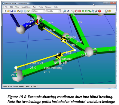
Ventilation Ducting and Blind Headings
In most mines, a number of blind or ‘dead end’ headings will exist. By model definition, a blind heading cannot carry airflow, as it does not have a continuous path of airways leading to and from each end. In many real cases however, these headings are effectively ventilated by auxiliary ventilation duct, and often need to be simulated within a model. Auxiliary fans blowing into ventilation duct are moving air from one part of the mine to another and often much of the heat and moisture for a mine comes from auxiliary ventilated areas that need to be simulated as part of the overall mine heat balance.
To satisfy a model requirement for a continuous air pathway, ventilation duct needs to be included as a separate airway. For clarification, this airway is best placed outside of the mined airway, and sized according to true ventilation duct size. The ventilation duct airway will carry air to the blind heading face. The blind heading airways will carry airflow back to a model junction, and then join any other airflow beyond the blind heading.
The DUCT construction tool (in the drop down option box next to the DRAW button) will automatically construct a duct airway parallel to a SELECTED series of airways. Once constructed, a fan or fixed flow just needs to be added to one section of the duct to simulate flows.
Hint : Specify the air type of ventilation duct to a different type and colour. Airway types can be displayed independently, and the duct visibility can be turned on or off to improve visibility of the model.
In some mines, airways may connect to other parts of a mine which are not simulated or included in the model. The airflow to or from these other parts must be included into the local model. To include airflows to areas not simulated or included in the current model, simply run a single airway off the main model, assign a Connect to Surface attribute under the Edit Formand then enter either a fixed flowor fixed pressure to simulate airflow to or from the area. Ensure the direction of the airway is correct.
Layers are a way to individually layer or identify and view parts of a model separately from other parts of the model. Some examples may include a stope system, an orepass or ventilation raise system, a workshop area, or any other collection of airways. Note that there is no requirement for the user to utilise viewing layers. They are only present to allow easier manipulation and viewing of a model. The ‘Metal Mine’ example in the Ventsim > File > Demonstration menu shows an example of layers.
Layers work by allowing the user to 'overlay' multiple layers of airways or information on a screen. By doing this, unnecessary detail can be 'turned off' so only airways of interest are viewed.
Layers may be made active or displayed using the Display Manager. Layers names can be changed from the Edit Box by clicking the button adjacent to the layer name.
Primary Layers
Primary Layersconsist of up to 250 layers. It is intended that the Primary Layers be used for identifying types of airways. For example, Layer 1 could be Primary Shafts, Layer 2 could be Main Airways, Layer 3 - Raises, Layer 4 - Stopes, Layer 5 - Minor Airways etc.
Secondary Layers
Secondary Layers, also consist of 250 discreet layers. It is intended that the Secondary Layers be used for isolating parts of a model that could be viewed independently from the rest of the model. As mentioned above, this could include working areas, stope, raises, declines or any other feature of interest.
There is no limitation on the number of airways belonging to a layer, however an airway can belong to only one secondary and one primary layer. Primary layers and secondary layers can be set and viewed independently of each other.
See the Metal Mine example (BLUE_SKY.VSM) examples that comes with Ventsim Visual.
Hint : To quickly save and recall a ‘layer state’ use the Save View function to save and recall views with the Primary and Secondary Layers settings.
Using Layers
The easiest way to use Layers may be to create the model first (all airways will default to Layer 1 of both Primary and Secondary Layers, and then editing individual or group airways to change the layers to the desired number.
Hint : The Edit Box has a function which will select and group all similar airways (for example all round airways with a diameter of 3.0m. This can provide a quick way to group edit and change layers for multiple airways.
New airways constructed will inherit the layer numbers of the airway they are constructed from. If no airway exists, new airways will use the default layers set in the Display Manager.
Hint : Because primary and secondary layers can used together, this creates an opportunity to create a filter using both layer systems. If for example, primary layers were assigned as different regions of a mine (North, South, East and West for example), and Secondary layers was defined as different functions (Shafts, Ramps, Ore drives for example), then by individually setting the Primary and Secondary layers, the following examples could be easily viewed.
- All ramps in the North Mine
- All ore drives in the East and West mine.
- All ramps and shaft in all mines.
The information in this Chapter explains only the basic techniques to establishing working ventilation models. To create a truly representative ventilation model, airway sizes and resistance must be accurately established; ventilation controls (such as doors or walls) must be placed in the model with correct resistances, and many other important factors such as shock losses considered.
For further information,
- See the Tutorial part of this manual
- Check the www.ventsim.com website for newsletters and forum information.
- Seek a suitable Ventsim Visual™ training course to undertake advanced training in the product.