AUXILLIARYVENTILATION AND DUCTS
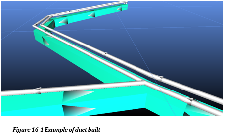
The auxiliary ventilation duct building function in Ventsim Visual provides an opportunity to model complex auxiliary duct arrangements in a mine model. Auxiliary duct in mines is essential to ensure quality fresh air reaches areas of the mine without flow through ventilation, which in most cases will be blind headings.
While auxiliary duct modelling is not a requirement for all models, the modelling of auxiliary fans and duct may be important to ensure adequate ventilation is delivered to key area, that the correct size duct and fan is used for a given length of duct, and that the impact of heat, humidity and fumes generated in auxiliary ventilated areas is correctly modelled on the remainder of the mine network.
Simulation of contaminants through underground mines can be difficult to predict, particularly if simulations are required to take into account the complex
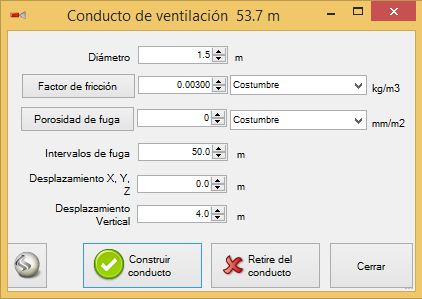
The vent duct builder box requires a number of values to be entered
Diameter
The diameter of the duct
Friction Factor
The friction factor of the duct. This can be directly overridden with a custom value, or additional friction factors can be added to the drop down list in the Preset > Friction Factor section of the program settings
Leakage Porosity
A leakage factorrepresenting the portion of the duct surface with holes, compared to the total duct surface.By default this measurement is in mm2 / m2, which could also be considered as ‘hole parts per million’. Higher values represent higher leakage. Placing a zero (0) in this box represents no leakage. Modelling leakage will increase model size and simulation complexity, therefore leakage should only be specified if it is specifically required to be modelled.
Ventsim offers a number of default porosity factors in the drop down list, however these are subjective and can be altered in the Preset > Leakage section of the program settings.
During simulation, leakage will demonstrate reducing airflow further along the duct away from the fan. Fan pressures and duct diameter, together with leakage factors will influence leakage amounts. Leaked air is returned to the airway at the position it is leaked from the duct.
Leakage Intervals
This specification is an internal instruction to Ventsim to build a leakage path (an invisible duct) into the airway at frequent intervals to allow air to leak back into the main airway. The resistance of this path is calculated automatically and is a function of the leakage factors and the leakage interval. In most cases it will not alter the simulation result significantly, however smaller leakage intervals will theoretically give more accurate results, but will increase the clutter and complexity of the display. For longer ducts, a minimum of 50m is suggested.
Offset
Specifies where the duct will be built in relation to the airway. It is advantageous to build the duct outside of the main airway as it is easier to see and manipulate. For example, if the main airway is 5m high, then a Z Offset of 5m will place the duct at 5m above the centreline of the airway. Do not use an offset of (0, 0, 0) as this will overlay the duct on the airway centreline and will simulate correctly.
Build Duct
starts the duct building process. A duct and leakage paths are place on a single group to allow the system to be selected with a single Select click in future.
Modify Duct
Modifies existing selected ducting with any new factors entered into the duct builder. Note that the leakage intervals cannot be modified. If this is required, the duct should be removed and re-built.
Remove Duct
Deletes any existing selected ducting from the model. If normal airways are also selected, then this function will only delete ducting and leakage paths.
Hint – Things you may want to do next
Place a suitable fan at the start of the ducting airway
Consider placing an obstruction in the main airway if the duct is significant in size, and airflows along the main airway are high.
When duct is created, a pathway will be built into the duct to allow it to draw and deliver airflow to the underlying airway.
To ventilate a duct, simply EDIT the start of the duct airway with the EDIT toolbar button (do not SELECT the duct first as the entire duct will be selected) and then use the FAN tab to place a fan or a FIXED flow in the duct.
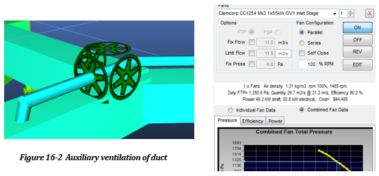
Pressurised or Suction Duct?
The direction of the fan controls whether the duct is pressurised or in suction. To change the direction of the installed fan after placement, simply use the REVERSE toolbar button to change the direction of the fan section of the duct. The entire duct airflow direction will then reverse after the next simulation.
Inline Fans
If a duct has multiple fans installed at different positions (a common practise for long lengths of rigid duct), then additional fans can simply be installed at locations along the duct, by using the previous method to install fans or fixed flows. If the duct is built with leakage, leakage can travel too or from the duct either way depending on fan and suction pressures.
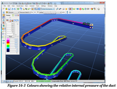
HINT : Using the TOTAL RELATIVE PRESSURE colours, the user can determine if the duct section are under pressure or suction.
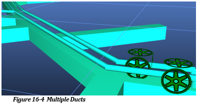
Multiple Ducts
If more than one duct is to be built along an airway, then the OFFSET function can be used to ensure the ducts are separated and will simulate correctly.
For example, if two ducts are required, the first duct can be built with a HORIZONTAL offset of ‘-2’ and the second duct can then be built with a horizontal offset of ‘2’. This ensures that either duct sits on opposite side of the airway and that they can be independently simulated.
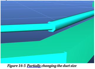
Multiple Sizes
If ducts require different sizes midway along the duct length, then this can be altered by selecting the duct portion that requires a different size, and then using the EDIT toolbar button to modify the duct size. Because duct is automatically GROUPED when created, to select only a section of the duct, either use the SELECT fence function, or ensure the CTRL key is held down while selected to override the GROUP functionality.
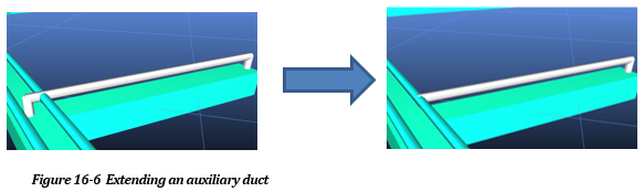
Extending Duct
To extend duct or create new tee-sections and junctions it is normally recommend to remove then rebuild the entire duct with the new section. Alternatively, it is possible to build only the new section of duct with the duct builder tool, however the connection section of the duct that join back to the airway will need to be manually removed with the DELETE button, to ensure the duct does not ‘dump’ the air back into the airway at the new join.
For example, in the picture below, a new auxiliary duct was created to extend into a new airway to the right of the main airway an duct. The duct builder created the duct with a connection back into the main airway. To ensure this duct is correctly joined, the connection must be DELETED and the remaining end of the duct MOVED back to the main duct and joined.