Fans are an important part of the modelling process. Correct entry of data for fan curves describing the pressure and flow performance at different fan duties is essential for accurate simulation.
The fan database is accessible from the TOOLS > FANS menu. The fan database allows editing, adding and deleting of all fans in the model fan database. Up to one thousand (1000) fans and the associated fan curves may be entered into the fan database. A display for each fan curve and data will be presented when a fan is selected from the display list.
The Edit > copy and paste functions can be used to copy data to or from another program (for example a spreadsheet).
Caution should be taken when deleting or modifying a fan, as any model which may use the deleted fan number, will not simulate correctly.
The fan name is entered or chosen at the top from the pull down menu. To enter a new fan, select File > New
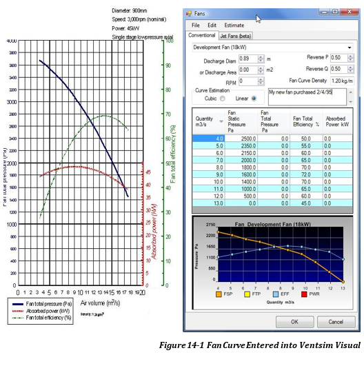
At a minimum, fan curve points for quantity and either fan static or total pressure must be entered for each fan. Other curve information such as efficiency and power can also be entered to assist Ventsim Visual™ in estimating fan power and heat.
Density is an optional parameter, which will assume a default value if not specified. In Ventsim Visual™ Advanced, fan performance is adjusted for density changes in the mine. Most manufactures supply fan curves at a standard density, however different densities can be entered for the fan curve if required.
Diameter
Diameter is also an optional parameter describing the exit diameter of a fan. This may be the diameter of the fan casing or an evasé if fitted. Ensure the fan curve entered is for the specific fan configuration (check with your fan manufacture for this). Adding or removing an evasé from a fan for example can significantly change the fan performance within Ventsim (although the fan total pressure curve will remain similar). Where only a static curve is available, the diameter can help estimate velocity pressure from the fan and the associated power consumption.
Where only fan total pressure is entered, the fan diameter can help estimate available fan static pressure, a consideration for the performance of surface exhaust fans. Finally, the fan diameter can also help estimate new curve points for the fan database, if either the fan static or total curve is unavailable. See the fan database section for more information.
Hint: It is recommended that where fan pressure curves are provided without an evasé (which is normally how fan manufacturers provide the curves as mines may mount the fan in different configurations), any evasé effects can be independently modelled by using the edit box options to place an diffuser in the airway.
Fan speed
Fan speedis a manufactures reference to the normal speed of the fan operation for the specified fan curve. The number is not directly used during simulation and will not influence simulation outcome. The percentage fan speed can however be adjusted in the EDIT box.
Fan Reversal
ReverseP and ReverseQ modifies performance for fans run backwards for an emergency situation. Most manufactures will not supply these figures as fans are not generally designed to do this (although some fans can be designed to perform better in reverse than others). These figures ideally need to be derived experimentally be measuring actual fan performance with blades running in reverse. Ventsim Visual™ initially defaults to 0.5 for both (50% of maximum pressure and 50% of maximum airflow).
Curve Estimation
The method used to estimate curve data between specified fan duty points. The cubic spline method estimates a curved data path between fan points. If only a few points of data are available, this may produce a better estimate of fan duty, however the method may be limited by sudden changes in curve data point direction. Ensure sufficient points are available to produce a smooth non-reversing curve.
The linear method predicts a straight path between points. This method is slightly faster during simulation, and if the maximum number of fan points (10) are entered, it should provide sufficient accuracy in most cases.
HINT: It is important that pressure on the curve is not permitted to bend over in a U shape (or upside down U), otherwise the simulation may oscillate between two pressure points. Stall regions of fans should be omitted for this reason.
Comments
Comment box is included to describe more information about the setup or configuration of the fan. It is not used for simulation.
Point Table
Fan Point Table : The table will allow direct entry of fan curve data. Fan curves will be constructed as data is entered. Points can be submitted non-sequentially, and will be automatically rearranged when the fan is re-loaded or saved.
As a minimum, Ventsim requires at least airflow, and a Fan Static Pressure or Fan Total Pressure point. Other information such as efficiency or power can be calculated by Ventsim using default settings, however it is recommended to enter one of these values if available to enable more accurate power and heat calculations.
To calculate fan power within a model, Ventsim Visual™ needs either a fan efficiency curve or a fan power curve. If neither of these curves is available, the default fan efficiency will be used from the Settings menu. If both efficiency and power curves are entered, Ventsim Visual™ will preferentially use the fan power curve to calculate absorbed fan power.
Where both Fan Static and Fan Total pressure curves have been entered for all fans in the database, Ventsim will automatically use Fan Total Pressures for simulation calculations. Unlike Ventsim 2.0, the simulation method is no longer selectable.
Ventsim will only use Fan Static Pressure for simulation if a fan does not contain a Fan Total Pressure curve.
Simulation Handling of Exit Velocity Pressure Losses
Exit Velocity Pressures occur on any airway or fan discharging air to the surface atmosphere. When considering fan pressure requirements, the exit velocity pressure loss is added to the mine resistance system pressure losses to calculate fan total pressure requirements. Fans must therefore provide sufficient total pressure to overcome both the mine resistance and the surface velocity pressure losses.
If only Fan Static Pressure curves are used in a simulation, the exit velocity pressure is ignored.
If some fans have only Fan Static Pressure and others have Fan Total Pressure curves, then Ventsim will simulate using a ‘Mixed Pressure’ method, where exit velocity pressure are ignored for all airways EXCEPT for surface exits that contain fans with Fan Total Pressure curves.
Total Pressure Method
The use of fan total pressures (fan static and velocity pressure) is considered the technically correct method for simulating airflows, as both static and velocity pressures contribute to airflow through an underground mine. Ventsim Visual™ can help predict a fan total pressure curve from an existing static pressure curve using tools in the Fan Database Editor.
The total pressure method assumes the full fan total pressure is available to ‘push or pull’ air through a mine. The method also considers system velocity pressure losses to the atmosphere (for example from exhaust shafts) and incorporates these into the simulation. The fan total pressure method relies on the user accurately considering fan exit losses with appropriate diffuser sizes, shock loss factors and resistances, as total fan pressure is never fully available to pressure the underground air flow. Fan outlet configuration, outlet flow direction changes and the inclusion of diffusers (which boost fan static performance and reduce exit losses) or other exit devices such as fan shutters need to be fully considered if they have not been incorporated into the fan curve, otherwise the model may over predict the available pressure and flow for the model.
To use the Fan Total Pressure Method, ensure all fans contain a Fan Total Pressure Curve. If any fans have only a Static Pressure curve, then the simulation will automatically switch to the Static Pressure Method.
Static Pressure Method
A more traditional approach is to use fan static pressure, which assumes that fan velocity pressure is wasted and does not contribute to the system ventilation pressure and flow. While this is not technically correct, this assumption removes some of the criticality of defining accurate exit losses, and while exit losses should still not be ignored, the resulting simulation will provide a more conservative result to simulation estimates of pressure and flow. The Fan Static Pressure (FSP) method ignores system exit velocity pressure losses and for a primary (surface) fan driven model systems, there is negligible difference between the FSP and FTP methods (as the FTP methods considers velocity pressure losses as part of the system pressure). However where underground booster fans contribute to a significant portion of ventilation flow, the difference between the two methods will increase.
To use this method, all fan curves used from the database should have a static pressure component. As with the FTP method, the fan database form has tools to assist the user in estimating FSP curves if not available.
Mixed Pressure Method
The mixed pressure method maintains compatibility with Ventsim Classic 3.9, which allows both pressure types (static and total) to be used for fans in models. The mixed pressure method is similar to the static method, in that it does not consider system velocity pressure exit losses. Fan pressure curve types can be specified for each fan location in the model. This may be of assistance if some static or total pressure curves are not available for the fan, and the user does not wish to estimate a curve. The mixed pressure method is considered to be the least consistent method to use, and should be avoided if possible.
Ventsim Classic 3.9 models will be automatically imported into Ventsim Visual™ as a ‘mixed pressure model’. Ventsim 3 will automatically select the pressure simulation method based on the type of fan curve pressures available in the fan database for simulation. The type of simulation method used is stated in the RUN > SUMMARY.
Fans used in Auxiliary Ventilation Duct
Unless discharge losses are manually considered, only Fan Static Pressure curves should be used for duct pressure and airflow calculations, as the velocity pressure exiting the duct is considered wasted.
For this reason, when a fan is placed in a ventilation duct, Ventsim will only use the Fan Static Pressure curve. If only a Fan Total Pressure Curve is available, then Ventsim will attempt to calculate the Fan Static Pressure Curve, based on the fan diameter or area, or if this is not available, from the size of the duct the fan is place in.
Should I Use Static or Total Pressure?
Most fan manufactures supply one or both types of pressure curves. Ventsim Visual™ differs from Ventsim Classic 3.9 in it can use fan total pressures (FTP), fan static pressures (FSP) or a mixture of both.
Using FSP curves will ignore the fan velocity pressure (FVP) portion contribution to model pressures, but will also ignore any system exit velocity losses to surface throughout the model.
Using FTP curves will include the FVP portion, but will include system exit velocity pressure losses as part of the model system total pressure.
The case for Fan Static Pressure Simulation
It is technically correct for simulations to use fan total pressure (FTP) curves for fan installations. Fan total pressure however is not always converted into useful ventilation energy due to outlet losses from fan installation configurations.
Traditionally, Ventsim Classic 3.9 has encouraged users to utilise fan static pressure (FSP) curves for modelling. Using FSP curves excludes the velocity (dynamic) component of fan pressure curve which is therefore assumed not to contribute to the overall system pressures in a model simulation. To partly offset the lack of fan velocity pressure inclusion, the system exit velocity pressures (the velocity pressure loss to the model from air exiting from shafts or other exhaust airways) are also not included by Ventsim Classic 3.9 in calculating overall system pressure. While these two factors partially cancel each other out, using Static curves for underground fans is likely to give a slightly conservative system pressure and airflow if fan exit (shock) losses are modelled identically for both an FSP and FTP case.
When designing a model, this may be advantageous to provide contingency for design simulations. In addition, use of FSP curves is less reliant on accurately modelling fan exit shock losses, and provides a greater contingency for design airflow. In general, they may be more suitable to use for a less experienced user.
The case for Fan Total Pressure (FTP) Simulation
FTP Simulation will allow Ventsim Visual™ to utilise the full fan total pressure curve for model system pressures. Provided fan exit shock losses are modelled to consider the fan installation and exit airflow orientation, then this method should provide more accurate results. In addition, as Ventsim Visual™ will consider system exit velocity pressures allowing fan exit diameters, airway surface exhaust sizes or evasés sizes are adjusted to simulate the effect of on surface exhaust airways and mine system pressure.
Note: Increasing fan diameters or including diffusers in Ventsim Visual™ for underground installed fans will have no automatic effect on model simulation results, as it will not change the surface velocity pressure exit losses. It may however decrease shock losses at the fan exit, which if modelled in Ventsim Visual™ by changing airway shock loss will result in improved fan performance.
Evasé / Diffuser Hint: If the Fan Total Pressure Method is chosen, the effect of diffuser size on surface exhaust shafts can be examined. Simply click on the surface airway, and select ‘diffuser’ and place a size large than the fan or airway. Alternatively, you can construct a short enlarged surface connection airway which will produce a similar effect to including an evasé option in an airway.
In Summary
In most cases, if fan exit shock losses are modelled are modelled correctly, the Fan Total Pressure (FTP) method is the bestoption to use.
Estimate Tools Menu
The tools menu contains a number of functions to assist in estimating fan static or total fan curves as if either one is unavailable, as well as fan total shaft efficiency and fan absorbed power if either one is unavailable. This may be required if only a Fan Static Pressure (FSP) curve is available, and you wish to simulate the model using a Fan Total Pressure (FTP) curve.
Ventsim Visual™ will use the outlet diameter of the fan to calculate the velocity exit pressure of the fan, and thereby calculate the missing static or total pressure curve.
To estimate absorbed power, Ventsim Visual™ will calculate theoretical power using total pressure and airflow. Note that none of these estimation methods take into account shock losses, resistance and compression factors which will slightly affect calculated pressure and powers. It therefore should be used as a guide only, and is no substitute for an accurate fan manufactures curve if available.
Estimate Fan Curve
Quickly estimates 10 evenly spaced points of fan curve duty from as few as 3 entered points. The estimation method will use the Cubic Spline method to add the additional points. This method should only be used if additional fan curve data is not accurately available.