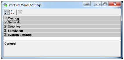
Settings provide control over a large number of parameters used in Ventsim for simulation, graphical display and file handling. Settings are normally saved specifically for the file in which they are modified for, but can be shared with other files using the INHERIT function, or the MASTER LINK function.
Defines the mining and ventilation cost components of a model. These figures are used in calculating optimum airway sizes, and total ventilation cost to run a modelled ventilation system.
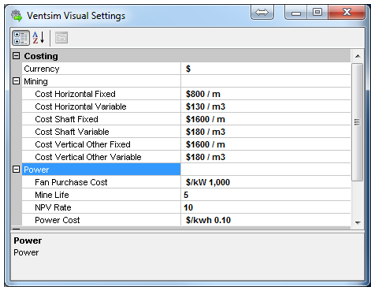
Currency
The symbol used for the local region currency value. This symbol will be applied in text displays and reports. Ensure all costs defined in this section are set in the local region current value.
Cost Horizontal
The cost of mining a unit volume of rock for horizontal or inclined airways.
This figure is an approximation used in the global optimisation routines to calculate efficient airway sizes. If a mine has an approximate cost per linear distance (eg per metre) for each tunnel size, this can usually be approximated back to a fixed cost per metre and a variable cost per m3 which is largely consistent over different airway sizes. Ventsim uses both the fixed and variable component in calculating total airway cost.
Cost Shaft
The cost per unit volume for mining vertical or inclined ROUND shafts. As with horizontal costs, this can be approximated if the linear cost of vertical airway mining is converted to a fixed linear and variable unit volume cost. Ventsim uses both the fixed and variable component in calculating total airway cost. Ventsim assumes any airway with a slope greater than 45 degrees is defined as a vertical airway.
Cost Vertical Other
The cost per unit volume for mining vertical raises that are NOT ROUND. The cost basis for a raisebored airway (round) and a blasted vertical area (eg a winze or Alimak raise) are normally very different, hence this category allows costs of different types of vertical development to be differentiated. Ventsim assumes any airway with a slope greater than 45 degrees is defined as a vertical airway.
Fan Purchase Cost
The purchase cost is an approximation of a fan total cost per unit of power. For example a cost estimate of $1000 per kW, would mean a fan of 30kW in size would cost $30,000 to purchase. This figure is used in the optimisations to estimate fan costs for different fan power requirements. This cost should be calculated to include the electrical infrastructure and installation costs as well as the fan purchase cost.
Mine Life
The expected average mine life of airways in the mine. This figure is used by the optimisation to estimate to power costs consumed over the life of an airway.
NPV Rate
The discounted rate of future costs to determine the present value of expenditure on power over the life of the mine. Values higher than zero (0) will decrease the significance of (discount) future cost savings, placing more importance on initial capital costs such as the airway mining cost and the fan purchase cost.
Power Cost
The cost of power supplied to the mine. The power cost is used to calculate the ventilation cost of running a mine model, and applied to all fans, fixed quantities and fixed pressures. The power cost is local currency unit dependent. Total power costs for mine model will be displayed as a factor of this value.
HINT : To gain the true operating cost of a ventilation model, users should consider including a maintenance and depreciation component in the power cost to cover the future cost impact of maintenance, repair and replacement of ventilation infrastructure. A value of 15% – 20% additional cost is typically used.
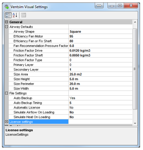
General factors describe default airway sizes and settings when first building a model, as well as file saving and loading behaviour in Ventsim.
Airway Defaults Various defaults used by Ventsim in establishing airways without defined dimensions.
Airway Shape
Default shape of airway.
Efficiency Fan Motor:
Default fan motor efficiency to apply to calculated fan shaft power to estimate the electrical power absorbed by the fan motor. In most cases it will be around 95% for direct drive electrical motors, or as low as 80 – 85% for offset or gear drive fans.
Efficiency Fan Fix:
Default efficiency factor to apply to motor shaft power calculations for fixed quantities and fans without efficiency or power curves.
Friction Factor
Default friction (K) factor to apply to new airways
Friction Factor Type
The number of the friction factor type to use on a default airway
Primary Secondary Layer
Default view layers to set to new airways.
Reversing Default Resistance
Default resistance to apply if resistances are set in airways which have reversed airflow AND the ‘restrict’ reverse airflow button is pressure. This is only applied if no reversing resistance already exists for the preset item. For example a resistance for a door may be 10 during normal flow direction, but may reduce to 0.5 when the airflow is reversed and the door swings open. Once again, this figure is ONLY applied if the ‘restrict reverse airflow’ option is chosen in the EDIT box, AND there are no pre-existing reversing resistances set in the resistance preset spreadsheet.
Layers – Primary and Secondary
Default layers to apply for new airways.
Size Width, Size Height, Size Area
Default size of new airways. Imported DXF and text files without specific airway size will also be set to these values
Hint : Airway defaults are normally only applied if airways are constructed without connection to other airways. Where airways are connected to existing airways, they will INHERIT the settings of the airways the new airways is connected to. This behaviour can be modified from the EDIT > NEW AIRWAYS menu item.
Auto Backup
Forces Ventsim to make a backup of the currently worked model every 5 minutes. If the program crashes, or is forcibly exited, the backed up model will be loaded automatically next time the program is run.
Warning – if the model has become corrupted for some reason, there is a possibility that the auto-saved model may also be corrupted. For this reason, it is recommended that a model be regularly saved to ensure that good working copies are available as backups if required.
Maximum Airway Numbers
Automatically performs an heat simulation when the file is loaded. This will update heat simulation summary parameters and a number of calculated heat parameters only available after a simulation
Maximum Reference Elements
Automatically performs an heat simulation when the file is loaded. This will update heat simulation summary parameters and a number of calculated heat parameters only available after a simulation
Alters license activation settings which may be required to allow Ventsim to access the internet to validate licenses. Ventsim normally uses Microsoft Internet Explorer settings to access the internet, however on occasions third party programs like Ventsim may be denied direct access, requiring the proxy name and proxy port address to be entered manually.
These values can also be adjusted in the License Manager form.
Graphics Settings Control the various aspects of the screen graphics and presentation.
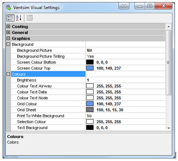
Background Picture
Sets a preset or custom picture to the background of the visual display. This may provide some visual flair for presentations or may simply suit the users preferences. An option exists to use a preset background (current CLOUDS or GROUND), or a custom background picture can be displayed by simply dragging a picture file from windows on to the screen.
Background Picture Tinting
Tints the background picture using the Screen Colour Top and Bottom settings. Note that a black screen colour will totally hide the pictures, while a white screen colour will fully show the picture in natural colours.
Background Colour Bottom and Top
Colour of upper and lower halves of background. The colours are smoothly blended to provide a gradient effect. Lighter colours may be more appropriate for presentations and report.
Brightness
Controls the relative brightness and intensity of the colour displays on screen.
Grid Colour
Colour of grid lines.
Grid Sheet
Colour of semi-transparent edit plane sheet shown during vertical drawing operations.
Colour Text Data
Colour of the airway data. Text colours may need to be adjusted to provide contrast if the background colours are adjusted.
Colour Text Airway
Colour of the airway text names and error messages. Text colours may need to be adjusted to provide contrast if the background colours are adjusted.
Colour Text Node
Colour of the airway node names. Text colours may need to be adjusted to provide contrast if the background colours are adjusted.
Print to White Background
Instructs the program to make the background white when printing a graphics model to a printer or saving the image to a file.
Selection Colour
The colour of selected airways. The default colour is yellow, however sometimes this colour may not be as visible with lighter colour backgrounds.
Text Background
The colour behind text on the screen if transparent text is not used.
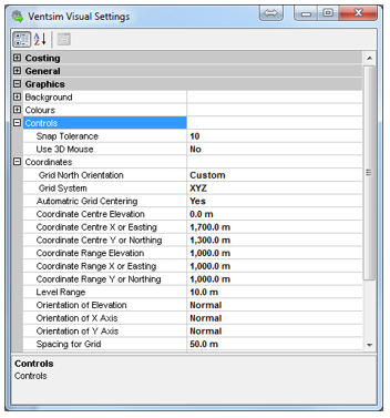
Snap Tolerance
Adjust the willingness of the Ventsim cursor to adjust or join to other airways while drawing or moving airway items. For finer control (less propensity to connect to close airways) reduce this number (minimum 1, maximum 100)
Use 3D Mouse
Turns on an option to use a Connexion™ 3D mouse. This type of input allows for models to be rotated, panned, and zoomed with a single control, leaving the regular mouse free to operate menus and selection duties. This option will have no effect if a Connexion™ 3D mouse is not present.
Grid North Orientation
Defines the direction of grid north on the screen. Therefore, if grid north direction is defined as UP, then the Northing coordinate numbers will start lower from the screen bottom, to higher numbers towards the screen top. If a GRID NORTH system is not chosen, then this setting will show CUSTOM.
Grid System
Most mines use a GRID NORTH system. Ventsim’s coordinate convention when using grid north coordinates is Easting, Northing and Elevation in that order. If another type of system is used, then an XYZ system can be specified, which allows for orientation of coordinates in any direction. Some Ventsim CLASSIC models use a custom system and in this will likely be automatically set when a Ventsim Classic model is imported.
Coordinate Centre
Defines the centre of the grid system from which the grid lines will be drawn. Note that this can only be specified if Automatic Grid Centering is turned OFF (otherwise the centre numbers will be automatically adjusted when the model is viewed or reloaded).
Level Range
The range of elevations to show around a single selected level. Selected levels may be chosen from the RIGHT CLICK mouse popup menu, and limit the range of airways data shown on screen.
Orientation of Elevation, X Axis, Y Axis
This option should only be used for CUSTOM grid orientation. Grid NORTH orientations do not require these settings to be adjusted.
Spacing for Grid
The spacing between grid lines on the screen.
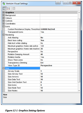
Custom Resistance Display Threshold
Controls the display of resistance icons where airways have been assigned a custom resistance. Only airways with a resistance above the threshold will have an icon displayed.
Transparent Icons
Shows transparent sides for icons over airways.
Anti-aliasing
An advanced graphics option (not supported by all graphics card) which smooths the appearance of the edges of solids to give a visually more appealing look. The option may significantly slow some graphics cards or cause graphics irregularities. By default, it is set to FALSE.

Backface Culling
Removes hidden surfaces from the display. This may make older graphics cards more responsive in displaying complex graphics.
Hide Text While Rotating
Hides text while model is rotated or zoomed. Very large models with lots of text can slow or make smooth rotation movements unresponsive. Use this option to hide text and make rotation movement much smoother.
Rotation Inertia / Damping
Ventsim model rotation results in a short period of continued rotation after the mouse is released. This is purely for visual appeal and is provided to give models the illusion of ‘weight’ and solidity. The speed at which rotation is damped can be adjusted or turned off using these settings.
HINT: To allow the model to rotate freely without stopping, choose a damping level of zero (0), or HOLD THE CTRL key down when rotating a model with the mouse.
Show All Arrow/ Node/ Text data.
Hide or shows arrow, node and text data by default. This can be used to improve display clarity by removing unnecessary graphical details. Note that this function can be overridden from the View menu options or the RIGHT click context menu options for text and other graphical items.
Maximum / Minimum Frame Rate
The rate at which to update the screen graphics. To conserve laptop battery power, the minimum frame rate option is available to reduce power when Ventsim Visual™ is not the active program in Windows.
Airway Scale
Scales airways graphically so they appear larger or smaller than the specified dimensions. This does not change the calculated airway size. A factor of ‘1’ is normal scale. Factors larger than one will enlarge airway graphics while factors smaller than ‘1’ will shrink airway graphics. This function may make very large extensive models larger and easier to see, or conversely can make very small model (eg lab scale apparatus) also easier to see.
Size Data Node Airway Text
Size of airway text displayed on model. Larger text sizes are generally clearer to read, however excessive data may clutter display.
Size Node, Icons, Arrows
The size of the nodes, icons and arrows. Note that the size reduces in wireframe mode to improve display legibility.
Size Node Icons/Arrows
The size of the nodes, icons and arrows. Note that the size reduces in wireframe mode to improve display legibility. In Solid mode, Icons and Nodes will not be reduced smaller than the airway size.
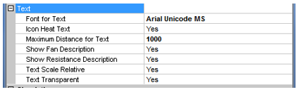
Font for Text
Allow selection of the type of FONT to display on the screen.
Icon Heat Test
Display text on icons with heat sources.
Show Heat Text with Airway Text
Shows the thermodynamic setting names on the airways they are attached to.
Maximum Distance for Text
Hides text beyond a defined distance from the display front. For large models, this can speed up display.
Show Fan Description
Display text showing fan name description
Text Transparent
The background for text characters is shown as a solid colour, or transparent. Turning off text transparency can improve clarity of text graphics, but will obscure the airway graphics behind the text.
[TRUE] Text labels backgrounds are transparent and show graphics under the label.
[FALSE] Text label backgrounds are solid and do not show graphics underneath. In some cases, this may improve the legibility of text.
Text Scale Relative
[TRUE] Reduces the size of text labels relative to distance away from view camera. This make close airways larger and more legible and distant airway text smaller. Simulation - Airflow.
Airflow
Simulation airflow settings directly influence how the airflow simulation operates.
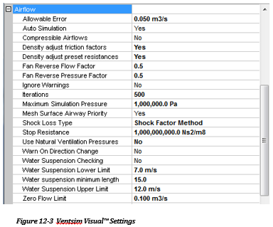
Allowable error
Defines the level of accuracy Ventsim must resolve down to before an acceptable solution is displayed. This should normally be set to less than 0.1 m3/s error. If a final analysis is required it may be advisable to set this to 0.01 m3/s or lower. The smaller the value, the more accurate the simulation process, but the longer it may take.
Auto simulation
Automatically performs an airflow simulation after every modification to a model. This will conveniently display airflow amounts and directions without having to simulate the model. For large models, or models undergoing extensive modifications, it may be preferable to turn this function off, as it will slow down editing and view functions.
Compressible Airflows [Advanced]
Use compressible airflow simulation techniques.
Compressible airflow has a significant influence when simulating deeper mines. In deeper mines (greater than 500m) or when heat simulation is used, it is recommended that compressible airflow be set to True.
When set to True, Ventsim Visual™ will assume compressible air, and adjust air densities, volumes and fan curves according to airway depth and corresponding density. In the Advanced version, temperature effects on density are also taken into account when Heat simulation is run in conjunction with air simulation.
Airflows and fan curve performance after simulation is shown according to the density of air at the location of the airway.
Density Adjust Friction Factors
Enables the simulation to adjust the friction factors to the local airway density. As resistance is a factor of friction, this will in turn adjust the airway resistance value. This setting is set to YES by default.
When set to YES, all preset friction factors are assumed to be specified at a standard density of 1.2kg/m3. If compressible airflows are enabled, the factor will be adjusted to the simulated local air density, otherwise the factor is adjusted to the standard environment density setting.
If this setting is not enabled or the airway EDIT form has set the value to ‘Already Adjusted’, then the actual value entered in the preset will not be adjusted.
Density Adjust Resistance Factors
Enables the simulation to adjust the preset resistance values to the local airway density. Preset resistance values do not use friction factors, therefore any friction factor setting is ignored.
When set to YES, all preset resistances are assumed to be specified at a standard sea level density (1.2kg/m3) and will be adjusted to suit the local airway conditions. If compressible airflows are enabled, the preset value will be adjusted to the simulated local air density, otherwise the value is adjusted to the standard environment density setting.
If this setting is not enabled or the airway EDIT form has set the value to ‘Already Adjusted’, then the actual value entered in the preset will be used.
HINT : Density adjusted friction and resistance values are a potential source of confusion. Most text books will quote friction and resistance values standardized to a 1.2kg/m3 air density. If standard values are used, ENSURE that both of the Density Adjust options are set to YES
If resistance or friction values are measured locally however, then the values obtained are only valid for the density at which they are measured. To use measured values in Ventsim, you will need to consider one of the following options.
OPTION 1 : If all preset values are measured at the true mine density and will not be used or duplicated elsewhere in the mine, then simply set the “ density adjust” setting for resistance and/or friction values to ‘NO’
OPTION 2 : If only some values are measured and other values are standardized to 1.2kg/m3, then you will need to use the EDIT form setting to set individual airways to ‘Already Adjusted” (the check box next to the resistance or friction value)
OPTION 3 : To avoid the potential confusion of Option 2, you may want to simply convert all of your measured values (at the local mine density) to a 1.2kg/m3 standard and set both settings to YES. This also has the benefit of allowing the setting to be used elsewhere in the mine at different densities.
Fan Reverse PFactor, Fan Reverse QFactor
Defines the default reverse fan performance relative to the original fan curve for the pressure and quantity of a fan running in reverse. These factors decrease the performance of fans set to run in reverse (for emergencies for example) in the EDIT box. Note that the default values may be overridden by values directly placed in the Fan Database for individual fans.
Ignore Warnings
[TRUE] Ventsim Visual™ will ignore all warnings related to No Entry or No Exit errors found during simulation (airways with no other airways joining)
[FALSE] Ventsim Visual™ will only ignore airways which have been set to Allow Closed End in the Edit box. Any other ‘orphaned’ airways will cause the simulation to show warnings.
Iterations
Sets the number of attempts Ventsim Visual™ can take to achieve an acceptable error, before the program abandons the simulation process.
Maximum Simulation Pressure
The maximum pressure the simulation will allow between airways before a simulation error is reported. This error may indicate unreasonable fixed flows or resistances which interact and cause large pressure changes in the model.
Mesh Surface Priority
Modifies the Ventsim Visual™ simulation algorithm to give mesh forming priority to surface connected airways. This normally ensure rapid solving of model simulations, however for models with extensive surface connected airways this may cause simulation balancing issues, and turning off this option may give better results.
Defines the shock loss method to use. Ventsim Visual™ can be set to calculate shock losses using the equivalent length method, or the shock factor (X) method. Shock loss calculations are necessary to estimate pressure loss due to air turbulence cause by a change in airway direction, a junction or a change in airway size. Note that changing this value in an existing model will result in Ventsim Visual™ requesting to recalculate the shock losses using the alternative system.
The equivalent length method requires the user to estimate an equivalent extra airway length required to approximate pressure loss due to shock.
The shock factor (X) method uses a calculated factor derived from both empirical and calculated changes in airway areas and velocities. Both methods are described in any number of ventilation texts.
Once the method is set, the Edit Box will require an appropriate shock loss value for each airway. The Edit Box can accept a manually entered number, but also has a number of preset values, as well as an AUTO function which will force Ventsim Visual™ to attempt to calculate a shock loss factor or an equivalent length.
Stop Resistance
Defines the minimum resistance at which Ventsim Visual™ will completely stop all airflow in an airway. All preset resistances above this value will cause airflow in the set airway to completely stop. Only one Preset Resistance value should be greater than the Stop Resistance value. This function artificially restricts airflow and has the potential to cause simulation problems if used on too many airways. The simulation will check and ensure that only one (or nil) preset resistances are greater than this value.
Use Natural Ventilation Pressures
[TRUE] Forces Ventsim to calculate natural ventilation pressures derived from air heat and density differences in the underground model. Natural ventilation pressures can sometimes produce unstable simulation air flows due to dynamic changes in airflow affecting subsequent heat balance simulations. This is discussed further in the Heat Simulation section. If this problem impacts heat simulation, providing natural ventilation pressures are not critical it is suggested to set to it to False to produce a stable simulation.
[FALSE] Ignore natural ventilation pressures. Where heat simulation is not required, or natural ventilation pressures are not likely to be significant in a mine, it is suggested that this setting be set to FALSE.
Warn On Change Direction
If set to TRUE, and an airway is specified in the EDIT form with a FIXED DIRECTION, Ventsim Visual™ compares airway directions before and after a simulation and alerts the user which airways have airflow that has changed direction during simulation.
Water Suspension Checking
If set to TRUE, Ventsim Visual™ will perform a check on all up casting vertical or semi vertical (>45 degrees) airways. The water suspension phenomena occurs on water droplets where the up casting air velocity friction is counteracted by gravitational forces, forming a suspended column of water droplets which can greatly increase shaft resistance and pressure. This can only be overcome by reducing airflow velocity allowing water to fall to the shaft bottom, or increasing velocity to carry the water out of the top of the shaft. The exact critical velocity depends on shaft size and geometry, as well as water droplet size and geometry of entry into the shaft.
Water Suspension Upper and Lower Velocity
The upper and lower limits at which Ventsim Visual™ will flag a warning if water suspension checking is optioned. Warnings do not affect simulation, but simply alert users to potential problem areas.
Water Suspension Minimum Length
Water suspension is unlikely to be a problem in shorter shafts. This setting allows the simulation to ignore shafts that are less than a defined length.
Zero Flow Limit
The flow at which Ventsim Visual™ assumes ‘zero’ flow. This function does not directly affect simulation, and is simply used to determine whether airways are displayed when the ‘zero flow’ graphical option is used to hide airways with no flow.
The default contaminant values and factors to use in simulation. In most cases these values can be overridden in the Edit > Contaminant box.
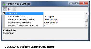
Contamination Unit
An arbitrary unit defining the volume concentration value of the contaminant simulation. Ventsim defaults to a unit-less value, which normally represents a percentage, however any volumetric portion unit such as ppm or mg/m3 could be used. Results of the simulation shown will be representative of the original value entered in the contamination value field.
Default Contamination Value
The default amount of contamination to place in an airway if the contaminant tool button is clicked. For steady state simulation, this would normally be the maximum concentration expected through the model unless recirculation or upstream contaminant sources are present.
For dynamic state simulation, this should be considered the average concentration of the contaminant volume to be cleared.
Diesel Particulate Emissions
The default diesel emission factor to use, if the preset heat sources do not have a specified factor. It is normally recommended that preset heat sources each have their own defined diesel particulate emission value. See DPM Simulation for further information.
Dynamic Contaminant Threshold
The value at which dynamic contaminant simulation will stop if every airway in the mine is below this number. It is suggested this threshold should be set to a number equivalent to safe access for the area.
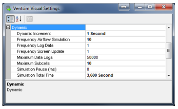
Dynamic simulation factors control simulation parameter required during dynamic simulation or when using the VentFIRE™ option.
Dynamic Increment
The increment at which Ventsim will advance the dynamic simulation. Smaller increments result in more accurate simulation and greater sub cell formation, however will take proportionally longer to simulate.
Warning – because of the way sub-cells work, it is not recommended to use large increments, as this will result in a loss of fidelity and accuracy in dynamic modelling. If airflow travels the length of an airway faster than the time increment, then the movement of cells through that airway is capped at the time increment, resulting in a small inaccuracy in time calculated to travel through the airway. Extensive occurrences of airways like this will cause simulation inaccuracies, generally resulting in slower dispersion times than actual.
Chasm Consulting recommended increments of one second (or less) where possible, and does not recommend increments more than 10 seconds for most conventional models.
Frequency Airflow Simulation
The frequency per increment at which airflow simulation will occur if selected. For example, a frequency of ‘10’ will perform an airflow simulation every 10 dynamic increments. Airflow simulation is an intensive calculation and for larger models it is recommended to increase the frequency factor (which will decrease the actual frequency) of airflow simulation to reduce simulation time.
Frequency Log Data
The frequency per increment at which data from the simulation will be collected for airways with a monitor in place. For example, a frequency of ‘10’ will collect data once every 10 increments.
Frequency Screen Update
The frequency at which the screen will be updated and graphically show the progress of the simulation. For example, a frequency of ‘10’ will display the graphics every 10 increments iterations. Lower numbers will result in a smooth display update, but will slow down simulation, particularly for large models.
Maximum Data Logs
The number of data points available for recording monitor location results during dynamic simulation. For length simulations or models with a large number of monitors, this may need to be increased. If a simulation exceeds the available number of points, it will ignore the overflow.
Maximum Subcells
The number of sub cell divisions that airways are divided into during dynamic simulation. Each sub cell moves independently through a model during simulation, collecting gases, heat, and contaminants. Cells movements and speed is controlled by the air simulation.
Note : Ventsim will always target the maximum number of sub cells, however the number of cells cannot be more than the time it takes to travel one increment of time. Therefore, for example if an airway passes air from start to end in 10 seconds, and the dynamic increment is 5 seconds, then a maximum of only two sub cells could be placed in the airway. Smaller dynamic increments will generally allow more sub cells to be used, resulting in more accurate, but slower simulation.
Simulation Pause (ms)
For small models, the simulation may progress too fast to visually track changes. A simulation pause (in milliseconds) can be entered to slow simulation down. For larger models, it is suggested to keep this pause to zero (0) to prevent unnecessary simulation delays.
Simulation Total Time
The time period for a simulation to complete (in seconds). For example, 7200 is equivalent to running the dynamic simulation for two (2) hours. At the end of the simulation time, Ventsim will ask if the user wishes to continue the simulation.
Simulation Environment [ADVANCED]
The environment factors describe values used by physical items within the model. They are critical to identify the base starting points of a ventilation simulation, or providing default air or heat simulation parameters to airways that do not have specific values set.
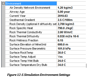
Air Density Model Environment
Defines the default air density to use in the model if incompressible flows are used (this is standard behaviour with Ventsim Visual™ Standard and optional with Ventsim Visual™ Advanced). All airways, resistance, friction factors and fan curves will be automatically adjusted to this air density. There is no requirement to individually adjust fan curves manually – any fan curves simulated will be adjusted from the fan database defined curve density, and will show the adjusted curve in the Edit > Fan form.
Ventsim assumes a standard density of 1.2 kg/m3 for predefined friction factors and resistances. Unless specified otherwise, these factors are adjusted to the density specified in this option.
Note that if Compressible Flows are used, the model air densities will be different through the model. Compressible airflow simulation ignores this value and uses the Surface Barometric pressure value as a basis to calculate air densities. Setting this value with Compressible Flow set to ‘ON’ will automatically set the surface barometric pressure based on the entered value and the wet and dry bulb surface temperature settings (below). The air density of the airways through the model is based on the barometric and fan pressure at each location, and the calculated heat temperatures.
Current Year
The calendar year at which the simulation takes place.
Ventsim Visual™ uses this value to calculate the age of an airway underground, if the individual airway age is entered as a calendar year (such as ‘2005’ in the EDIT box). Where an airway age is entered as a time value (such as ‘3.5’ years), the Current Year value is ignored.
HINT Where true airway ages have been entered as a calendar year within a model, the Current Year setting is useful for ‘ageing’ a mine and determining future cooling requirements. Heat flow from virgin rock strata decreases exponentially over time as the rock is cooled, and future cooling requirements can potentially be lower than current cooling requirements as a result.
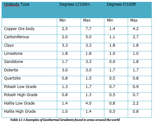
Geothermal Gradient
The rate at which rock increases in temperature at depth. This is assumed to be a linear value. Geothermal gradients show significant differences at different points around the earth, and can be as low as 1 degree Celsius per 100m to more than 10 degrees Celsius per 100m. This value should always be adjusted to suit the conditions at or near your mine.
Average Age
The Default Age of an airway opening in years. Airways without a specified age set in the Edit Box, will be assigned this default airway age. Establishing airway age allows Ventsim Visual™ to more accurately calculate geothermal heat flow into an airway. Geothermal heat flow decreases with airway opening age.
Wetness Fraction
The default fraction of airway rock surface that is wet. Most rock surfaces underground have some degree of moisture. The wetness fraction defines what average portion of rock surfaces are considered wet. A value of 0.01 would define a very dry airway, while a value of 1.0 would define a fully wet airway. This value will be assigned to airways without a set wetness fraction from the Edit Box, and directly affects the amount of moisture available to evaporate into the air passing the rock surface.
Rock Density
The default density of rock underground. This value is applied to an airway, if it has not already been set in the airway Edit Box. Rock density is a property which describes the mass of rock per unit volume. Rock density is used by Ventsim to calculate the thermal diffusivity of rock material. Rock Density is not required if thermal diffusivity has already been set. If this value is changed, the user will be prompted to allow Ventsim to auto calculate the rock diffusivity.
Rock Specific Heat
The default Specific Heat of rock underground. This value is applied to an airway, if it has not already been set in the Edit Box. Rock Specific heat describes how much heat must be absorbed or emitted to raise or lower the rock temperature.
Thermal Diffusivity
The default Thermal Diffusivity of rock underground. This value is applied to an airway, if it has not already been set in the Edit Box. Rock Thermal Diffusivity is a property which describes the ability of rock to diffuse or transmit contained heat over a unit area per unit of time. Rock with high thermal diffusivity more rapidly adjusts its temperature to that of the surroundings, because it conducts heat quickly in comparison to its heat capacity or 'thermal bulk'. Because diffusivity is directly related to density, thermal conductivity and specific heat by formula, rock thermal diffusivity is required only if rock density has not been set. If this value is changed, the user will be prompted to allow Ventsim to auto calculate the rock density.
Rock Thermal Conductivity
The default Rock Thermal Conductivity.. This value is applied to an airway, if it has not already been set in the Edit Box. Rock Thermal Conductivity is a property which describes the ability of rock to transmit heat through its mass.
Surface Wetbulb Drybulb
The Default Surface Temperature Conditions of air entering a mine. All air intakes into the mine are assigned the default surface temperatures. The temperatures and Surface Barometric Pressure are used to calculate the surface air density.
HINT: In rare cases, a mine may have multiple intake airways with a range of elevations so great that different temperatures may be present at each intake. As the Surface Barometric pressure is defined for a single Surface Elevation, Barometric Pressures will be correctly recalculated for differing intake elevations; however temperatures may need to be manually corrected. Temperatures can be adjusted by place a heat or cooling source at the inlet of intakes to produce differing temperatures.
Surface Pressure Barometric
The Barometric Air Pressure at the Surface Elevation.. The surface barometric pressure is important as Ventsim Visual™ calculates mine air densities from the surface barometric pressure and wet and dry bulb temperatures.
Surface Elevation
The elevation (or ‘reduced level’) where a specified point in the mine exits the surface. All other surface related settings (such as surface temperatures, pressures and rock temperatures) are assumed to be at this elevation.
If this value is set to zero (0), Ventsim will search and use the highest point in the model.
Surface Rock Temp
The temperature of virgin rock at the Surface Elevation. All virgin rock temperatures underground are calculated from this base elevation by using the Geothermal Gradient.
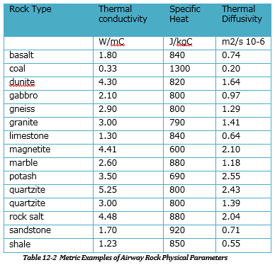
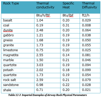
Warning – These are examples only. Rock characteristics vary widely for different rock types and locations. Where possible, characteristics should be measured by laboratory analysis.
Contaminant Density
The gas density of the contaminant gas of concern from the explosive reaction. For example, if Carbon Monoxide is the main gas of concern, then a gas density of 1.16 kg/m3 could be used. Ventsim uses this density figure to convert the yield mass into a volume.
Contaminant Yield Amount
The mass ratio of contaminant (of concern) produced per equivalent mass of explosive detonated. For example, if Carbon Monoxide was the gas of concern in an explosive detonation, tests by Orica reveal that approximately 0.015 kg of carbon monoxide is produced for every 1.0kg of explosive detonated. Therefore the contaminant yield for CO is 0.015.
Further information regarding contaminant simulation can be found in the Run > Contaminant section.
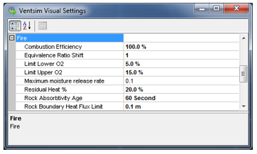
Combustion Efficiency
The portion of fuel converted to heat defined under the ‘Heat of Combustion’ of the fuel source.
Note: The combustion efficiency of an underground fuel fire will generally be less than 100%. Combustion efficiency generally depends on the availability of oxygen to all parts of the fire and the heat generated by the fire. In many cases, the efficiency may be a little as 75% or less, although if this is not known, using 100% is considered a more conservative approach.
Equivalence Ratio Shift
The amount to shift the equivalence ratio towards or beyond the fuel rich gas generating zone.
Equivalence ratio is the ratio of available oxygen to the fuel burn rate to produce a perfect stoichiometric reaction. An equivalent ratio of ‘1’ would mean that there was exactly enough oxygen provided to perfectly burn a defined mass of fuel. An equivalence ratio of less than one would mean that the amount of oxygen exceeds the rate at which the fuel consumes it (oxygen rich fire). An equivalence ratio of greater than one means that insufficient oxygen is available to burn the fuel mass, resulting in incomplete combustion gases and pyrolised hydrocarbons (fuel rich fire).
Note; For perfect combustion in an ideal environment, fires produce very little carbon monoxide where equivalent ratios are less than 0.5. The rate of carbon monoxide production increases as the equivalent ratio approaches 1.0, and the yield rate generally peaks at a ratio of around 1.3. Ventsim will alter the generation of CO2 and CO gases based on the equivalence ratio, and the combustion yield factors used in the preset.
For an underground fire in a confined place at extreme temperatures, even in the presence of a theoretically excess amount of oxygen, a fire can produce significant amounts of incomplete or ‘chemically reduced’ combustion products. To force Ventsim to produce higher amounts of carbon monoxide, the equivalence ratio can be moved towards ‘fuel rich’ results by adding a shift factor. If in doubt as to the behaviour of the fire, it is suggested to use a shift factor of ‘1’ or more to force the maximum amount of Carbon Monoxide to be produced.
Limit O2 Upper Lower
Ventsim will modify the defined fuel burn rate based on the oxygen limits to produce a more realistic fuel burn profile.
For example, most open flame sources will diminish significantly below 15% oxygen, and continue diminishing as oxygen levels reduce further. Between the upper and lower limit, Ventsim will limit the fuel burn to proportionally less than the defined amount set in the airway, reducing combustion rates linearly between the upper and lower limits. Combustion of the fuel will cease below the lower oxygen limit.
To disable this behaviour, set both limits to zero (0).
Maximum moisture release rate
Controls the maximum flow of moisture to a rock surface available for evaporative cooling in millimetres (mm) per second surface coverage. A default of 0.1mm is suggested.
Wetness fraction settings for rock influences evaporative cooling of airflow flowing past a rock surface. In the event of a fire, the rate of evaporation can easily exceed the rate at which water will replenish the rock surface. Therefore it is important to limit the flow of water otherwise the hot air from a fire will be artificially cooled at a rate much greater than would be possible in a real life scenario.
Residual Heat %
Maintains a minimum flow of heat from the fire source, even if insufficient oxygen causes combustion rates to fall below this level.
Heat from a fire does not immediately cease if the combustion is reduced or ceased by lack of oxygen. Significant amounts of heat may be stored within the combustible structure mass and may continue to be released even without direct combustion. To ensure the simulation continues to receive at least some heat during periods of low oxygen, this value can be set at a portion of the normal full combustible heat level.
Rock Absorptivity Age
The modified radial heat transfer age coefficient Ventsim uses for fire simulation.
Normal steady state heat simulation requires a rock exposure age (in years) to modify the exposed rock mass to a temperature closer to the long term air temperature.
For fire simulation, the rock mass surrounding the immediate airway is assumed to have cooled close to a long term air average, and the fire simulation assumes a rapid transfer of heat from the hot air back into the cooled rock mass. To facilitate this rapid transfer, the rock must be assumed in the (Gibson’s heat) transfer algorithm to be ‘freshly’ exposed again.
Note: A default value of 60 seconds is suggested, which provides rapid absorption for intense heat changes. Values lower than this can cause over prediction of heat absorption of very hot air.
For non-fire dynamic simulations, heat calculations can sometimes slightly exceed steady state estimates. If dynamic simulations are required to closely match steady state simulations, it is suggested to increase this value substantially (the second equivalents of days, weeks or even months).
Rock Boundary Heat Flux Limit
The thickness of rock which is directly influenced from short term dynamic heat changes.
This method allows an exposed surface rock layer of ‘skin’ to both store and release heat from rapid heat changes.
While actual rock in this situation will theoretically build up a complex graduated heat profile based on changing heat and air velocity, this simplified method assumes a single homogenous rock mass skin that absorbs heat evenly, but beyond which no significant heat passes. For short term dynamic simulation, this is a reasonable assumption.
INFO : As this ‘skin layer’ heats and becomes closer to the temperature of the heated airflow, the rate of heat absorption will decrease.
Conversely, if the fire heat reduces and air temperatures fall below the heated rock surface, this rock skin layer can rapidly release heat back into the airway airflow during simulation.
Use Gas Density for Air Simulation. Uses the relative density of different gas compositions to apply natural ventilation pressures to airflow during simulation. Gas compositions may be set using the gas options in the EDIT box, or from VentFIRE™ simulations.
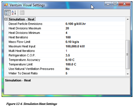
Heat [ADVANCED] Adjusts settings which directly influence how the heat simulation performs.
Diesel Efficiency
The efficiency at which diesel engine mechanical output is derived from the total heat of combustion of the fuel source. Ventsim uses this value to convert diesel engine power sources into heat during simulation. Ventsim assumes by default all diesel engine output power AND wasted inefficiencies enter the airflow as latent and sensible heat. The heat calculated from a diesel engine is
![]()
Heat Divisions Min/Max
Airway segment divisions for heat calculations.
The heat simulation process in Ventsim Visual™ progressively calculates heat along each airway by dividing it into smaller sections. Where airflow is very slow or an airway is very long, this allows the psychrometric process to continually adjust pressures, temperatures and moisture content, resulting in a more accurate simulation. Ventsim Visual™ automatically adjusts the number of divisions according to airflow velocity, airway length and heat inputs. The number of divisions used is restricted by the min and max values in the settings. Higher division values will theoretically give more accurate heat estimates but will increase the time required for simulation.
Multi Heat Iterations
Performs multiple airflow and heat simulations.
When set to more than one (1) performs multiple heat and airflow simulations, adjusting densities and airflows between each simulation. Manually pressing the HEAT simulation button has the same effect.
Heat simulation in Ventsim Visual™ Advanced is performed as two discrete simulations, first as an airflow balance, followed by a heat balance simulation. While the mass flow balance from the airflow simulation is kept constant during heat simulation, the new temperatures and air densities calculated after heat simulation, result in a theoretical mass imbalance of airflows. This can be corrected by a subsequent airflow simulation; however subsequent heat simulations will again affect the balance. This imbalance normally reduces with subsequent simulations, as temperatures and airflow changes reach equilibrium.
Multiple pass iterations can be set which will automatically force Ventsim Visual™ to simulate the model a number of times, to account for some of the potential imbalance. This will significantly slow down simulation time. Iteration values larger than one are usually unnecessary if a model has already been heat balanced, or if the HEAT simulation button has already been pressed a number of times.
HINT: Performing a multiple pass heat simulation may have value if the model shows some heat instability (changes in temperatures between simulations). Heat instability is often caused by unstable natural ventilation changes driven by conflicting changes in airflow, strata heat and evaporation.
For example a heat source which causes an increase in temperature may cause an increase in airflow due to natural ventilation – in subsequent simulations, the higher airflow causes lesser temperature increase from the heat source, which in turn reduces the airflow due to natural ventilation. Evaporation from strata moisture may also causing conflicting density changes, with strata heat density changes offset by cooling evaporation. The process may then oscillate between solutions for each heat simulation. As a final pass performing a multiple pass simulation of 10 or 20 (which may take a long time) may help resolve this instability.
Heat Iterations
Limits the number of internal iterations permitted by Ventsim Visual™ to converge and find an acceptable heat solution. Where recirculation occurs or high numbers of very low airflows are present, a simulation may take a large number of iterations to fully balance. In most cases, the main airflows will quickly balance, and even if the simulation fails to complete within the set number of iterations, this will usually be in the low flow airways which have little effect on the main flow airways. The status bar at the base of the Ventsim Visual™ window will show the progress of a heat simulation, including the number of iterations and the heat balance errors. Increasing the number of iterations may help resolved unbalanced models, but will take longer to simulate.
HINT: A leading cause of heat flow convergence issues is recirculating airways in low flow airways due to natural ventilation pressures. Natural ventilation pressures can create internal ‘eddies’ of air in disused or low flow airways which can affect heat simulation convergence. To prevent this, and speed up heat simulation, either turn off natural ventilation simulation (if natural vent pressures are not significant) or block disused airways so they simulate as no flow
Water to Diesel Ratio
For diesel heat sources, this value defines the amount of water emitted to the air as latent heat is per unit weight of diesel fuel consumed. Although the theoretical combustion reaction portion of water produced to fuel consumed is only around 1.1, the operation of a diesel machine in a mine environment results in a greater release of water into the air due to accelerated evaporation of water around the machine (from a wet roadway or walls for example), compounded by other sources such as handling of moist or wet material, wet exhaust scrubbers and cooling systems used by the machine, result in a much higher value. A value of five (5) or more is generally recognised as giving a more realistic result for water introduced to the air by mobile machines. Stationary machines may be closer to the theoretical value.
The default water to diesel ratio is used on all diesel sources in the model. To use values other than default, the sensible and latent heat will need to be entered separately instead of a single diesel heat source.
Diesel Particle Emissions
Describes the default amount of diesel particles emitted from a diesel engine, per unit of diesel engine power. This value is applied to diesel heat sources placed in a model, to assist in diesel particulate matter (DPM) simulation for the model. The value is highly dependent on the type of diesel engines, catalytic converters and scrubbers being used on the exhaust, as well as the type of diesel fuel used. In most cases, tests will need to be done on engine exhausts, or information gained from diesel engine manufacturers to find the correct value to use. Ventsim Visual™ will apply this default value to diesel sources which have not been assigned a specific emission rate. Specific rates for diesel equipment and airways that will override this default value can be assigned in the Presets or in the Edit box.
Temperature Limit
The temperature limit above which Ventsim Visual™ will halt simulation and display an error if it occurs. Temperature limits can be exceeded when too higher heat input is placed in an airway with not enough airflow.
Heat simulation uses a number of empirical formulas which are designed to work within a specific temperature range. In general, temperatures above 70 degrees centigrade will start to result in a reduction of accuracy of heat estimation.
Mass Flow Limit
The minimum mass flow that Ventsim Visual™ will perform a heat simulation on. Below this limit, Ventsim will assume the air is stationary, and adopt the local virgin rock temperatures as the air temperature. This value must be set above zero, as portions of the program which calculate heat and moisture derived from rock surfaces must have some airflow velocity to work. While there is some potential for heat imbalance errors by not taking into account low flow airways, it is generally small due to the limited heat energy flow able to be carried by these low flow airways.
Refrigeration COP
The ratio of output refrigeration power (kWR) generated by the refrigeration heat exchange process, versus the input electrical power (kW) required to produce this heat exchange. This factor is not used by the simulation, by rather by the power and cost calculation of a model in the Summary section.
Temperature Accuracy
Sets the temperature balance limit Ventsim Visual™ must achieve for all airway mixing at junctions in a model, to consider a simulation as balanced. If the balance is not achieved for EVERY airway and junction, iteration is performed until the iteration limit is reached or temperatures are resolved.
HINT : The smaller the temperature accuracy set, the longer a simulation may take to complete. In most cases, the vast majority of airways will fall well under this limit, and any temperature accuracy issues will be limited by very low flowing airways which have little impact on the main model.
Maximum Heat Input
Limits the amount of heat that can be put into a single airway. This is mainly included as a check to ensure excessive heat is not placed in an airway (such as a point heat source value accidently being entered as a linear heat value).
Recirculated Airway Limit [Advanced]
The number of recirculated airways beyond which Ventsim will first ask permission to simulate exact recirculation amounts. The simulation routine to calculate individual airway recirculation is complex and time consuming. If there are more than (say) 500 airways, this may take a minute or two to simulate. Therefore the option will be given to abandon the simulation, or simply show the airway which recirculate without actual % amounts. On faster computers, it may be desirable to life this limit, to prevent Ventsim pausing and asking permission.
Recirculation Limit Volume [Advanced]
The volume of air that is allowed to recirculate before the Check Recirculation routine flags a warning and initiates a full recirculation check.
Ventsim System Settings Ventsim Program settings control over-arching settings which influence all parts of the program.
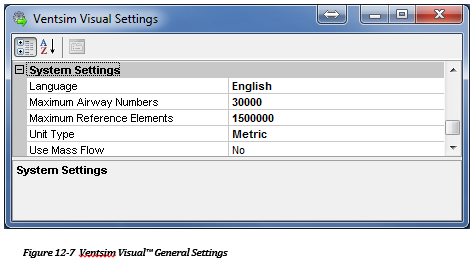
Unit Type
The type of units to use in Ventsim Visual. The program operates natively in SI Metric, with underlying calculations performed in metric units. To display imperial values and accept imperial input, set the unit type to Imperial. The imperial setting uses a conversion table to calculate the conversion from metric, and can be customised to suit mine preferences. The imperial conversion table can even be set to use a combination of Metric values by setting the program to IMPERIAL and then using the SETTINGS > UNITS menu to individually specify what units will remain ALWAYS METRIC.
Warning – the conversion table has set limits of decimal accuracy to convert from metric to imperial and back again. If the decimal accuracy is too low, some accuracy may be lost in the conversion process, and the value input as an Imperial number, may be returned slightly differently.
Use Mass Flow
Replaces fixed flow input in airway edit forms, with a fixed mass flow option. Some countries utilise mass flows to specify air quantities in mine ventilation.