Preset values provide a quick and convenient way to specify airway characteristics and parameters that may be commonly used in the ventilation model. Examples are resistances (such as doors or seals), common wall friction factors, shocks losses, heat sources.
The preset table also provides access to model primary and secondary layer names and colours, as well as air types, tunnel profiles, fans, wetness fractions and numerous other items used in Ventsim simulation.
Any preset value which is changed will be applied to ALL airways using that preset value. For example if a model has 10 airways using a resistance preset called ‘Rubber Flaps’ and the resistance for ‘Rubber Flaps’ is changed in the preset box, then ALL 10 airways using rubber flaps will have the new resistance applied when simulation is next performed.
Most items can be deleted by selecting the entire row (or a selection of rows) and pressing DELETE, or by selecting and deleting individual values. If a preset is currently in use, a warning may appear stating the fact, and the result it will have on the model. Ideally, presets should not be removed if they are currently in use.
The sort order of the preset values displayed in the spreadsheet, and displayed in forms in other parts of the program can be specified. All columns in the preset form can be sorted by Ascending or Descending by clicking the column header once or twice. For example, resistances can be sorted by name (by clicking the ‘Resistance Name’ column header, or by value (by clicking the value header).
In addition, row items can be manually sorted, by selecting the row and pressing the UP or DOWN arrow on the keyboard. The sort order will be retained next time the form is accessed and will be saved with the file.
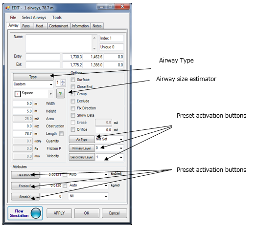
Preset items are accessed from the main TOOL menu, however most preset items can also be directly accessed from the EDIT form by pressing the appropriate preset button. When activated from the EDIT form, the currently used preset will be highlighted in the Preset form.
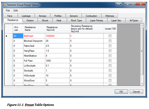
Up to 100 different resistance presets can be entered. Resistance presets can be applied to airways from the EDIT form. Any resistance entered in the preset will be applied to an airway during simulation.
It is important to note that underlying airway resistances due to wall friction WILL ALSO be applied in addition to the preset resistance. For example if a preset resistance of ‘10’ for a ‘DOOR’ is applied, and the airway has an underlying resistance of 0.015, then a total resistance of 10.015 will be applied during simulation.
The reversing resistance is an optional field which applies a different resistance should an airflow be reversed during simulation, and the ‘restrict airflow direction’ flag is chosen for the airway. Reversing resistances may be useful in situation where resistance increase (such as automatic doors closing, or flaps sealing) or where resistances decrease (such as doors swinging open automatically) when airflow direction changes. Such setups may occasionally be used to prevent recirculation or assist with emergency response design when fan direction may be reversed. If the value is left at zero (0), then a default reversing resistance (specified in the SETTINGS) will be applied if an airway is reversed AND the ‘restrict airflow direction’ flag is selected.
Up to 250 different friction factor presets can be entered or used. The friction values in the EDIT box can be applied as presets (entered in the preset form), as individual ‘CUSTOM’ values or as AUTO values which defaults to a value specified in the SETTINGS.
Shock equivalent lengths or shock factors can be entered in the shock preset area. The application of these factors will depend on which shock loss method is specified in the SETTINGS. The values for each shock item during simulation will be applied according to the method chosen. Only the value of the shock loss method currently used needs to be entered.
Up to 250 different heat, moisture and refrigeration sources can be entered. Each ‘Heat’ source can be a combination of different heat parameters (such as moisture and sensible heat combined). Airways with a specified heat source will have these values applied during simulation. The screen also shows the number of heat sources currently in use.
Layer Prim, Layer Sec, Air Type
The form shows current names for these items, and in the case of layers, whether they are being used or not. The names can be changed at any time, and new layer names and air type names can be added. Colour can be changed by clicking on the colour box. There are currently 250 layers and 25 airway types reserved for use.
Present a summary of current fans, and the basic characteristics of those fans (eg diameter, air density for the curve etc). While the fan curve data cannot be directly edited from this screen (you will need to go to the fan database function), the fan names can be changed as well as the other fan parameters. Fans can also be fully deleted from the model. A read only column states the number of fans in use in the model.
Airways presets allow a specific size and type of airway to be set with pre-defined dimensions, friction factors and profiles. Airways can then be quickly selected in the EDIT box to the preset airway type containing the preselected values.
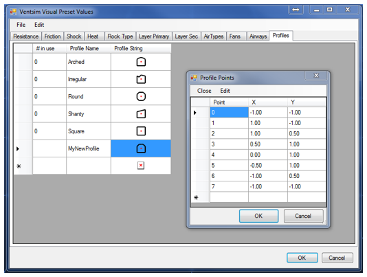
Profiles allow custom profile shapes to be entered into Ventsim. The first five (5) profile shapes – square, round, shanty, arched and irregular are preset and cannot be changed, however the profile string is shown to help users define new profile strings.
Profile strings are dimensionless coordinates centred around an origin point of (0,0). Airway profiles are intended to extend from (-1, -1) to (1, 1) which represents the full extent of the profile. The actual airway size of the profile is set in the EDIT box which then scales the profile to whatever size is specified. The profile shape is updated in the lower right corner, once the profile string is entered and re-selected.
To enter or add a profile, click on the Profile String cell on the profile grid. A data enter form will show allowing points to be entered or modified.
For example a square would have an X, Y profile -1,-1 ; -1, 1 ; 1 ,1 ; -1, 1, which represents the X,Y extents of all four corners around a centre point of 0,0. If this profile is chosen in the EDIT box when setting an airway, entering a width and height dimension of 5.0m would scale the profile accordingly. Note that there is no need to provide an area or perimeter. Ventsim automatically calculates the perimeter and area, based on the profile shape given.
Defines the wetness fraction options for underground airway wall wetness. Wetness fractions can be applied to airways in the HEAT section of the EDIT box. In general, wetness fractions closer to zero represent dryer airways and fractions closer to one (1) represent wet airways.
Lists the current sensors imported from the LiveVIEW™ option.
A selection of combustible products used in VentFIRE™ simulations. Combustible products are defined by the amount of heat released MJ/kg, the oxygen consumption (kg Oxygen per kg fuel burned) and the yields rates of various combustible products (kg combustion product per kg product burned).
Note that the yield of carbon monoxide is specified as a minimum and maximum. This provides some flexibility in the emission rates for oxygen rich and fuel rich fires. If the calculated equivalence ratio (ratio of fuel available per oxygen available) exceeds above (1) then the maximum CO value will be used in simulation. It the ratio falls below 0.5 then a value close to the minimum will be used. For ratios between these values, a value between minimum and maximum will be calculated, increasing towards the maximum value as the ratio approaches one (1). The equivalence ratio is not fixed and is constantly recalculated during simulation.
Defines the resistance of leakage of air from a Ventilation duct. The values define the area sum of holes per total unit area, specified as mm2 per m2 of duct. Because this ratio uses the same units, any number representation of the ratio x 1 x 10⁶ (million) could be used – for example parts per million (ppm).
Defines a mixture of gases that can be applied to airway gas simulation. If the total volumetric concentration of gases defined is less than 100%, then the remaining volume will be used during simulation to allow airway gases to volumetrically balance into the remaining void. The will retain the preset gas mixture of the defined gas value, but allow other undefined gases to changing depending on the airway gas content as simulation time.